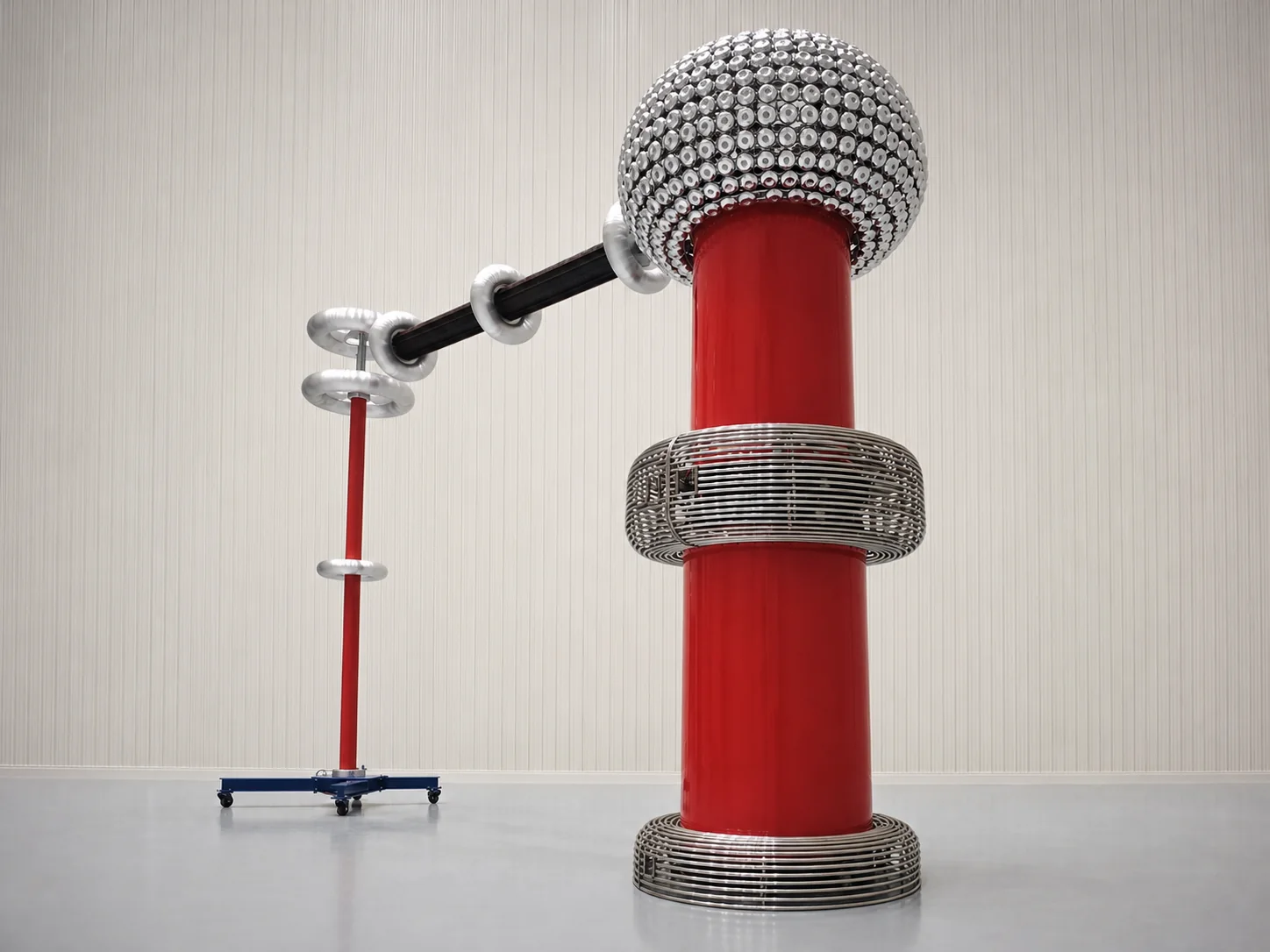
A transformer cannot be checked on arrival. It is checked at the plant, on a high-voltage test floor, before it is crated. Here are the test facilities of our qualified partner factories, the tests that are actually run, and the points where we are physically present.
The test plan identifies the facilities and competence needed for each test. Testing may be performed in the factory or by a qualified external laboratory, with traceable results for the relevant design or unit.
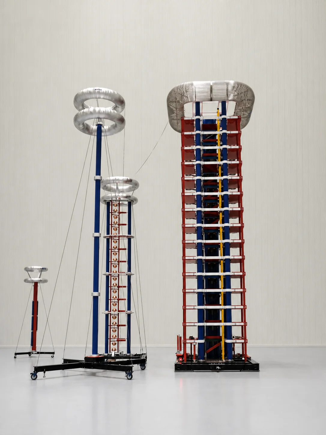
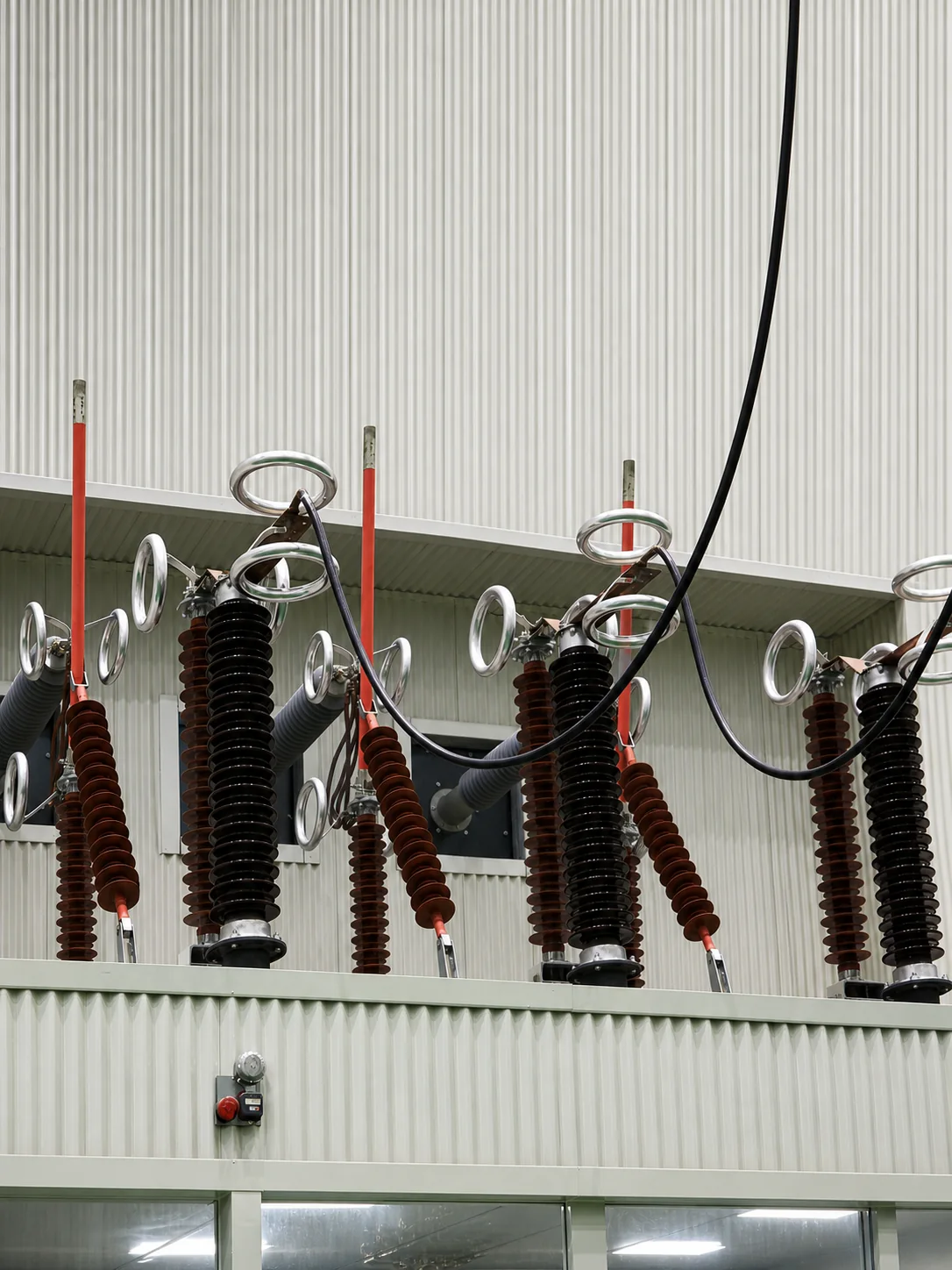
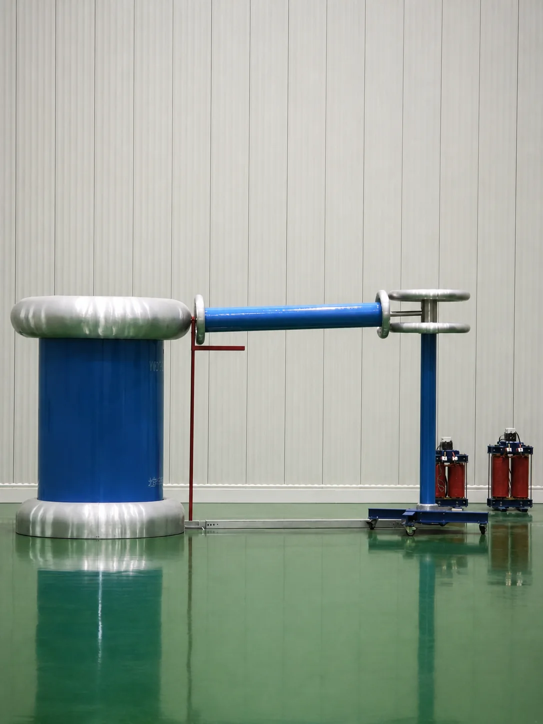
Routine tests as defined by IEC 60076-1 are performed on every unit, not on a sample. They are recorded in a named test report carrying the serial number of your transformer.
| Ratio & vector group | Ratio checked on every tap and the vector group (Dyn11…) |
|---|---|
| Winding resistance | Detects a cold joint, a broken strand, a wrong conductor section |
| No-load loss & no-load current | The value guaranteed against Tier 2 — this is where it is decided |
| Load loss & short-circuit impedance | Uk in %, decisive for parallel operation and fault-current calculation |
| Applied voltage (power frequency) | Withstand of the main insulation, winding to winding and winding to earth |
| Induced voltage | Withstand of the turn-to-turn and layer-to-layer insulation |
| Partial discharge (dry-type / cast resin) | Measured in pC; on a dry-type unit this is the number one ageing indicator |
| Leak tightness (oil-immersed) | Tank pressurised, gaskets and valves checked |
Type tests (temperature rise, lightning impulse, short-circuit withstand) and special tests: on a unit representative of the design, or to order. See the guide on FAT & witness testing.
A test report needs traceable results tied to the equipment. The agreed inspection plan identifies hold points, document reviews and any tests to be witnessed by the client or their representative.
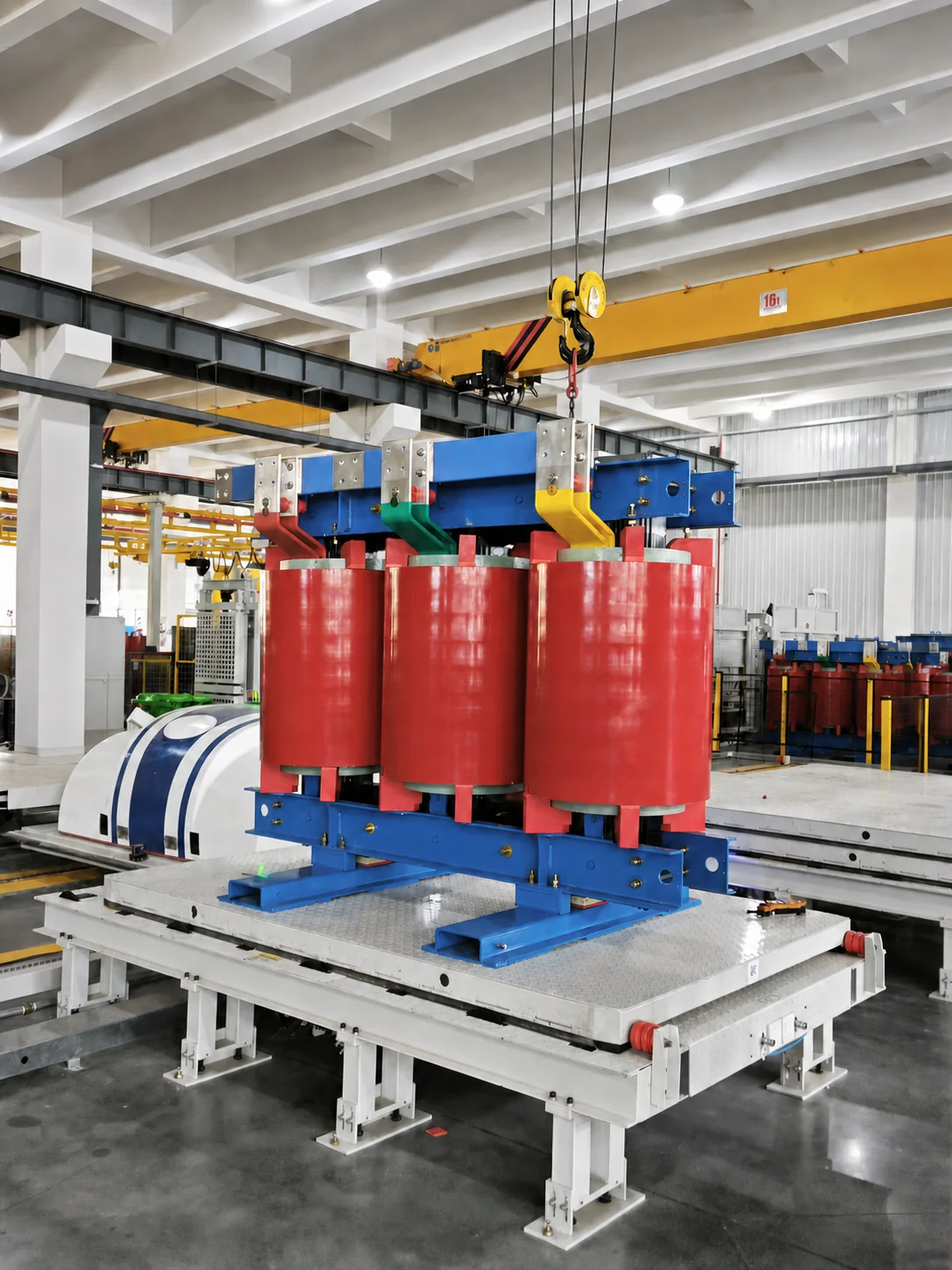
On request, these tests can also be witnessed by an independent third party (KEMA, TÜV, DNV, Bureau Veritas) or by your own representative. The option is selectable in the configurator.
A large share of the non-conformities we raise are not electrical. They concern the enclosure, the accessories and the marking — and they cost just as much to fix once the unit is on site.
Component detail on the cast resin and spare parts pages.
The accepted quotation sets the warranty duration, starting point and conditions.
General overview of the facilities and the approach. The exact test list, guaranteed values and acceptance protocol are fixed in the specification for each order.
Routine tests as defined by IEC 60076-1 are performed on every unit produced, and the test report carries your unit's serial number. Type tests (temperature rise, lightning impulse, short-circuit withstand) are performed on a unit representative of the design, not on every unit.
Witnessed routine tests can be arranged with the client, their inspector or an independent organisation. The test scope, notice period, location and cost are agreed in the inspection plan.
The hold point stops production: the unit can neither be packed nor shipped until the non-conformity is closed. A non-conformity report is opened, the root cause is addressed, and the affected test is re-run in full.
Yes, it is a routine test on cast resin units. The level measured in pC is the best early indicator of an encapsulation defect, and therefore of the real service life of the winding.
Quality control sits inside a wider compliance and warranty framework.
The workshop photographs on this page show manufacturing and testing facilities. They are not customer delivery references. Evidence is reviewed against the actual design and the supply scope of each project.
| Stage | Documents to agree |
|---|---|
| Before order | Technical schedule, scope, proposed inspection plan and list of evidence to be validated. |
| Before manufacture | Approved design documents and interface checks at the contractual milestone. |
| Before dispatch | Serial-numbered routine test report, nameplate, inspection records and packing checks. |
| At delivery | Agreed installation and operation documents, accessories list and transport records. |
Illustrative structure only — no actual measurements or certification.
| Field | Content |
|---|---|
| Identification | Manufacturer, design reference, serial number, rating, voltage ratio and connection group. |
| Test basis | Applicable standard and edition, procedure, date and instrument traceability. |
| Results | Winding resistance, ratio, losses, impedance and applicable dielectric / additional tests: specified limits, measured values and conclusion. |
| Approval | Inspector, deviations, corrective action, retest and release decision. |
Routine tests on every unit, hold points held on site, witness testing optional.
Configure a quote →